Why EV Energy Storage Cabinets Still Fail IP68—Even with FIPFG in Place
In EV battery pack and energy storage cabinet assembly, sealing quality increasingly defines warranty exposure, safety perception, and export readiness. Yet many production lines that already adopted FIPFG (Formed-In-Place Foam Gasket) continue to see inconsistent sealing performance, rework cycles, and IP rating failures—especially after vibration, thermal cycling, and long-term humid exposure.
This industry research report examines a practical route to stabilize seal integrity: combining ±0.05 mm high-precision dispensing, a dual-station flow-line design, and a high-pressure water–air cleaning system that removes trimming-related defects and improves gasket wetting and adhesion consistency. The perspective is process-first, data-supported, and aligned with how Tier 1 suppliers validate IP68 compliance.
The Hidden Root Cause: “Good Gasket Geometry” Doesn’t Guarantee a Good Seal
In typical cabinet sealing, teams focus on bead width, height, and continuity. Those are necessary, but field defects often originate before dispensing—during trimming, surface preparation, and particulate control. Microscopic debris, coolant residue, and edge burrs can create capillary leakage paths or reduce foam-to-substrate bonding, lowering real-world protection even if the gasket looks visually perfect.
Observed failure modes in EV storage cabinets (typical audits)
- Trimming micro-burrs cut or puncture the foam surface during compression.
- Oil mist & coolant films reduce surface energy and cause partial delamination.
- Dust or aluminum chips create “stand-off points” leading to local under-compression.
- Inconsistent edge radii amplify bead placement deviation, causing thin spots.
Practical takeaway: a stable IP68 strategy must treat cleaning and edge quality as part of the sealing system, not as a separate “finishing” step.
IP68 Sealing Expectations: What “Passing Once” Doesn’t Prove
While IEC 60529 defines IP ratings, high-volume EV programs typically add internal reliability gates: thermal cycling, vibration, salt-fog (for certain markets), and post-aging leak validation. In practice, the challenge is not the first test pass—it is maintaining the seal after stress and time.
| Validation Item | Typical Target in EV/Tier-1 Programs | Seal-Relevant Risk |
|---|---|---|
| IP68 immersion check | 1–3 m water depth, 30–120 min (program-dependent) | Localized leak channels from burrs/particles |
| Thermal cycling | -40°C to 85°C, 50–200 cycles (common ranges) | Expansion mismatch causes micro-gapping |
| Vibration durability | Random vibration profiles (vehicle platform-specific) | Fretting at interface if adhesion is weak |
| Helium/pressure decay leak test | In-line screening for seal repeatability | False rejects from surface inconsistency |
Industry note: many Tier 1 quality teams reference IEC 60529 for IP definition, but rely on additional internal reliability standards to reduce field returns.
A Proven Process Stack: ±0.05 mm Dispensing + Dual-Station Line + High-Pressure Water–Air Cleaning
The most reliable improvement seen in modern EV sealing cells comes from treating sealing as a closed-loop manufacturing system rather than a single dispensing step. Three elements reinforce each other:
1) High-precision dispensing at ±0.05 mm (path + bead control)
Precision in bead placement and height reduces thin spots and over-compression. In cabinet sealing, a ±0.05 mm motion/dispense accuracy is often sufficient to stabilize compression ratio across corners and tight radii—where most leakage events start. High repeatability also improves downstream automation like vision inspection and in-line leak tests.
2) Dual-station flow-line design (throughput without compromising cure window)
Dual-station cells typically allow one station to dispense while the other loads/unloads or runs verification, preventing “rush handling” that can distort fresh foam. In many lines, this configuration improves effective output by 20–35% versus single-station layouts, mainly by reducing idle time and decoupling manual interventions from the critical dispensing path.
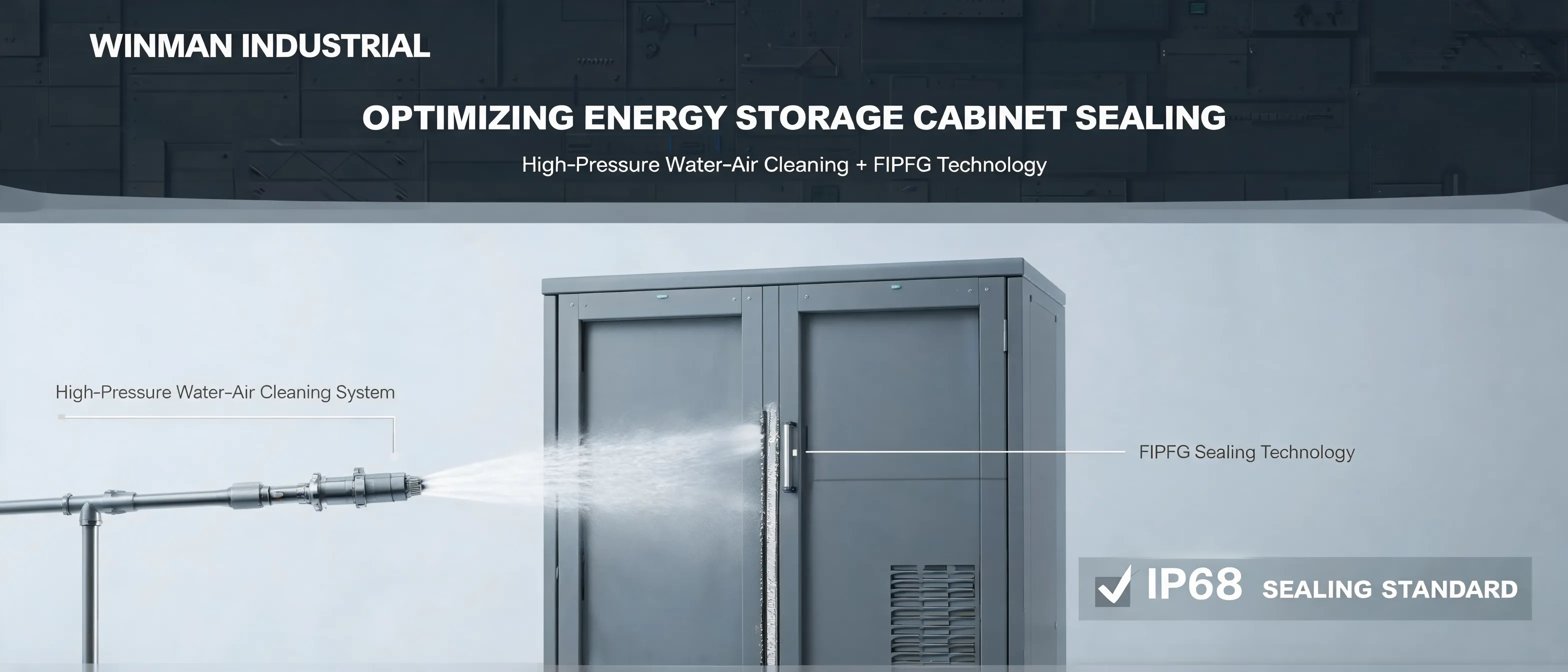
3) High-pressure water–air cleaning (removing trimming defects & improving adhesion)
This is where many sealing programs unlock repeatability. A high-pressure water–air cleaning system removes fine particles and edge residues after trimming, while controlling moisture via air-knife drying. Compared with wiping or basic air blow-off, water–air cleaning can reduce residual particulate and film contamination significantly; in practical deployments, lines often report 30–60% fewer leak-related reworks after implementing standardized cleaning + dryness verification.
Process Logic: How Cleaning Eliminates “Trimming-Driven” Sealing Variance
Traditional trimming leaves behind micro-burrs and embedded chips that are hard to detect visually. When the cabinet cover is torqued, those defects can locally reduce foam compression or create micro-channels. A well-designed high-pressure water–air cleaning step targets those issues systematically:
Suggested flow (engineering-friendly, scalable)
| Step | Purpose | Key Control Point (KCP) | Typical Metric |
|---|---|---|---|
| Trim / deburr | Geometry readiness | Edge radius consistency | Corner burr rate (%) |
| High-pressure water cleaning | Remove chips/film | Nozzle angle + coverage | Particle residue (swab test) |
| Air-knife drying | Avoid trapped moisture | Dryness verification gate | Surface moisture pass/fail |
| FIPFG dispensing (±0.05 mm) | Uniform gasket build | Path teach + speed stability | Bead width/height Cpk |
| Cure + assembly + leak test | Verification & traceability | Torque strategy + test method | First-pass yield (FPY) |
When this stack is deployed as a single engineering standard, factories typically see higher first-pass yield and more predictable IP68 performance, because the cleaning step removes the variability that dispensing precision alone cannot compensate for.
Case-Based Insight: What Changes After Upgrading to Water–Air Cleaning
In a representative EV energy storage cabinet program (metal enclosure + cover, FIPFG applied on the cover perimeter), engineering teams introduced a high-pressure water–air cleaning station between trimming and dispensing, while simultaneously tightening robot path accuracy to ±0.05 mm and migrating from a single station to a dual-station cell.
Reference outcomes observed in production stabilization (indicative)
- Leak-related rework rate decreased by approximately 40% within 6–10 weeks after process lock.
- Dispense defect calls (thin spots at corners) reduced by 25–30% after path optimization and fixture repeatability improvements.
- Overall throughput improved by ~28% after dual-station balancing and reduced operator waiting time.
- Audit stability improved: fewer intermittent failures in post-stress validation (thermal/vibration) due to better adhesion consistency.
These numbers are realistic reference ranges seen across comparable cells; actual results depend on substrate, foam chemistry, trimming quality, and verification method.
As many quality leaders summarize it: sealing reliability is primarily a controllability problem—the best foam and the best robot cannot overcome uncontrolled contamination and edge damage. This aligns with common guidance across manufacturing quality systems, where variation reduction typically outperforms “spot fixes.”
Process demo (video reference)
For a visual walk-through of a cabinet sealing line concept (cleaning → drying → FIPFG → verification), teams often use short internal videos for training and audit preparation. A public-friendly reference format can follow this structure: example process video search results.
Design Notes Engineers Ask About (and Should Decide Early)
Nozzle strategy and coverage mapping
Cleaning results depend on coverage, standoff distance, and edge targeting at corners and bolt regions. Best practice is to run a coverage map validated by swab tests, then lock nozzle positions as controlled parameters.
Dryness verification is not optional
Water–air cleaning must end with a measurable dryness gate (time + airflow + sensor/inspection). This prevents moisture from interfering with foam wetting and adhesion at the interface.
Path programming for corners and radii
IP failures often start at corners. Stable programs slow down at high curvature regions, maintain bead shape, and avoid over-acceleration that causes bead thinning. A dual-station setup helps keep these conservative parameters without sacrificing output.
Where Winman Industrial Fits: Practical Manufacturing Upgrades, Not Theory
In EV and energy storage cabinet manufacturing, decision makers often want one thing: an upgrade path that improves sealing stability without turning the line into an engineering experiment. Winman Industrial focuses on implementable sealing process solutions that combine cleaning, precision dispensing, and line design—so the sealing performance is engineered into the workflow rather than “inspected in later.”
For buyers evaluating energy storage cabinet sealing solutions, the most useful benchmark is not a single specification sheet; it is whether the supplier can help lock a repeatable process window and provide documentation suitable for Tier 1 audits and continuous improvement.
Ready to Reduce IP68 Risk and Rework in Your Cabinet Sealing Line?
Explore a practical upgrade route—high-pressure water–air cleaning + ±0.05 mm precision dispensing + dual-station efficiency—engineered for battery pack assembly and Tier 1 production realities.
Learn advanced sealing process solutions Contact technical experts for customized serviceInteractive Technical Exchange
Engineers and production leaders tend to face similar trade-offs. To make the discussion useful, readers can share three parameters (even in ranges), and the community can compare approaches:
- Substrate type (aluminum, coated steel, composite) and trimming method
- Target IP level and validation stack (immersion depth/time, thermal cycles, vibration)
- Current FPY and top 2 defect codes (leak point distribution helps)
Suggested prompt: “Where do our leaks start—corners, bolt zones, cable exits, or random perimeter points?”
FAQ (Buyer-Style Questions from Battery Pack & Tier 1 Teams)
1) Does high-pressure water cleaning introduce corrosion or moisture risk?
Not when designed with correct water quality control and a defined air-knife drying gate. The engineering focus is to ensure no trapped water remains in grooves, bolt pockets, or seam structures before dispensing and assembly.
2) Why is ±0.05 mm dispensing accuracy important if the foam compresses anyway?
Compression helps, but it cannot fix thin spots created by placement drift—especially at corners and short radii where the bead can stretch. ±0.05 mm-level control improves uniformity, reduces local under-compression, and simplifies in-line inspection thresholds.
3) What measurable KPIs should be tracked after upgrading the process?
Most teams track: (a) leak-test FPY, (b) rework loop time, (c) bead geometry Cpk at corners, (d) swab/particle residue audit results, and (e) post-stress validation pass rate (thermal + vibration).
4) Can dual-station design really improve output without increasing defects?
Yes, because it reduces operator-driven interruptions and keeps dispensing parameters stable. Output gains typically come from less idle time and fewer unplanned stops—not from pushing faster bead speeds that can distort gasket consistency.